

NEWS
NEWS
introduction about thermal characterization for reliable high power LED lights
24-10-2017
Die attach materials used in the combination of LED lights directly influence operating temperatures of LED lamp, and certainly we know that heat is the enemy of reliable LED components and LED lighting products. Higher thermally conductive materials, such as sintered nano-silver, allow an LED light to operate at lower temperatures. This influence leads to higher luminous flux, efficiency, color stability, and reliability. LED light developers should fully understand thermal dissipation to achieve the best performance. Here we will cover research that explains the thermal characterization process that can further guide LED packaging decisions.
For example, our LED work lights are predominantly cooled via conduction through the material stack to the aluminium heat sink outside. The die attach layer is one of many layers in the thermal stack, but it can serve as a hinderance if materials with sufficiently high thermal conductivity aren used. Typically, 10–30% of the electrical power an LED light consumes is radiated as visible light, while the rest is turned into heat. Basically, this heat leaves the LED light via conduction through the die attach layer stack.
The most common industry evaluation of LED thermal behavior is the junction-to-ambient thermal resistance. In this test, the whole LED stack is measured at once, without difference between various component layers. This method is sensitive to variations in the die, package layers, thermal interface material (TIM), and heat sink.
LED chips are adhered to a substrate with a die attach material. The die attach material forms an important link in the thermal path of the LED light to ambient environment. In many cases, the die attach material also forms the electrical connections. An LED chip affixed directly to a metal substrate is an example of chip-on-board (COB) architecture and is common in high-power LED designs. Heat generated at the LED junction conducts through the stack layers to reach the heat sink. These layers include the chip, die attach layer (Level 1), package substrate, package attach layer (Level 2), dielectric, and metal substrate.
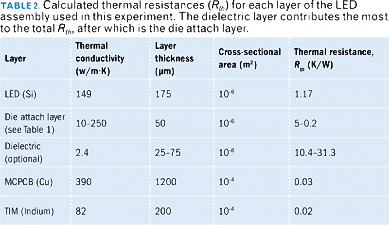
The layered structure of a single COB LED stack can be considered one-dimensional from the p-n junction through the die attach layer. After heat enters the metal substrate, it can spread flatly before it is conducted to the heat sink and then to ambient surrounding. Therefore, because of the small cross-sectional area of the one-dimensional stack, each layer needs to be highly thermally conductive (or, equivalently, have low thermal resistance; see Table 2).
The dielectric layer in a typical stack occupies the total thermal resistance of a packaged LED. For the experiment we will discuss here, we mounted LED chips with a die attach layer directly to copper pedestals in what is called an active substrate with no dielectric layer, which as you will see enabled high-sensitivity measurements.
The LEDs used for this experiment were based on aluminum gallium indium phosphide (AlGaInP) layers on silicon (Si) substrates. They were 1×1 mm in footprint and 225-μm thick. The typical operating current for the LED light is 350 mA with a forward voltage of 2.4V. The peak wavelength is 624 nm.
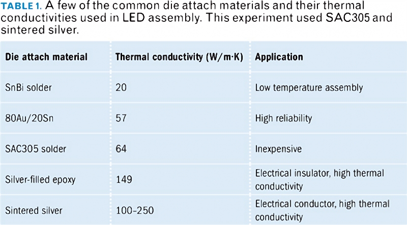
In this study, we sought to develop a test method to understand the influence of the die attach layer on the thermal performance of high-power LEDs. Die attach materials vary widely in their thermal performance, price, and intended applications (Table 1). We compared two die attach materials: a mid-performance, industry-standard solder alloy (SAC305) and a high-performance alternative (sintered nano-silver paste).
The thickness of the die attach layer, also called as the bond line thickness (BLT), is a key property of a LED light. Thicker BLTs reduces thermal stresses, but lead to higher overall thermal resistance. We measured the BLT of our LED lights via a vertical measuring microscope with follow-up cross sectioning to confirm the results.
LED COB substrates are typically made of copper or aluminum. These high-conductivity metals allow heat to escape before it enters the TIM and the heat sink. However, most LED substrates have a dielectric layer between the die attach pad and the metal core. This layer has comparatively high thermal resistance — so much so that the total thermal resistance of the LED stack is overwhelmingly dominated by the thermal resistance of the dielectric layer (Table 2).
In our experiment, we needed to measure the very small thermal resistance of sintered silver. With the dielectric layer at hand, the thermal resistance of a sintered silver layer was only 0.8% of the total thermal resistance, making exact measurement impossible. Solder die attach layers cover only 2.7% of the total thermal resistance when a dielectric is present, making these measurements difficult but possible.
Removing the dielectric gives a direct heat path to the metal substrate and greatly decreases junction-to-ambient thermal resistance. Without a dielectric, the sintered silver die attach layers contribution is 8.4% of the total stack resistance and solders contribution is 21.3%. This ten-fold increase makes the measurement possible with commercial off-the-shelf hardware.
The test we performed is based on JEDEC Standard EIA/JESD51-1 "Integrated Circuits Thermal Measurement Method Electrical Test Method (Single Semiconductor Device)," 1995. Because the forward voltage of a LED varies with the temperature of the p-n junction, it can be used as a temperature sensor. Also, LED lights produce much heat when they are operated at high power, so they can also be used as heaters. To use a LED light as a temperature sensor, it should be operated at very low current so that there is no internal heating. By quickly changing between high and low currents, we can use LED lights as test devices to measure the thermal resistance of all the layers in the die attach stack. If the switch between heating and sensing currents happens quickly enough, then the sensing current can be used to measure the temperature of the previous heating phase.
The die attach layer is an essential heat conduction layer in a LED light assembly and its performance strongly depends on thermal conductivity. While JESD51-1 is the standard for determining the total thermal resistance of an LED lamp assembly, we modified it to measure the bulk thermal conductivity of high-performance sintered silver. By assembling test samples without dielectric and using sufficient power switching, we measured the thermal conductivity of our sintered silver material and compared it to SAC305. Sintered silver die attach materials provide excellent thermal performance improvements versus SAC305 solder.
For example, our LED work lights are predominantly cooled via conduction through the material stack to the aluminium heat sink outside. The die attach layer is one of many layers in the thermal stack, but it can serve as a hinderance if materials with sufficiently high thermal conductivity aren used. Typically, 10–30% of the electrical power an LED light consumes is radiated as visible light, while the rest is turned into heat. Basically, this heat leaves the LED light via conduction through the die attach layer stack.
The most common industry evaluation of LED thermal behavior is the junction-to-ambient thermal resistance. In this test, the whole LED stack is measured at once, without difference between various component layers. This method is sensitive to variations in the die, package layers, thermal interface material (TIM), and heat sink.
LED chips are adhered to a substrate with a die attach material. The die attach material forms an important link in the thermal path of the LED light to ambient environment. In many cases, the die attach material also forms the electrical connections. An LED chip affixed directly to a metal substrate is an example of chip-on-board (COB) architecture and is common in high-power LED designs. Heat generated at the LED junction conducts through the stack layers to reach the heat sink. These layers include the chip, die attach layer (Level 1), package substrate, package attach layer (Level 2), dielectric, and metal substrate.
The layered structure of a single COB LED stack can be considered one-dimensional from the p-n junction through the die attach layer. After heat enters the metal substrate, it can spread flatly before it is conducted to the heat sink and then to ambient surrounding. Therefore, because of the small cross-sectional area of the one-dimensional stack, each layer needs to be highly thermally conductive (or, equivalently, have low thermal resistance; see Table 2).
The dielectric layer in a typical stack occupies the total thermal resistance of a packaged LED. For the experiment we will discuss here, we mounted LED chips with a die attach layer directly to copper pedestals in what is called an active substrate with no dielectric layer, which as you will see enabled high-sensitivity measurements.
The LEDs used for this experiment were based on aluminum gallium indium phosphide (AlGaInP) layers on silicon (Si) substrates. They were 1×1 mm in footprint and 225-μm thick. The typical operating current for the LED light is 350 mA with a forward voltage of 2.4V. The peak wavelength is 624 nm.
In this study, we sought to develop a test method to understand the influence of the die attach layer on the thermal performance of high-power LEDs. Die attach materials vary widely in their thermal performance, price, and intended applications (Table 1). We compared two die attach materials: a mid-performance, industry-standard solder alloy (SAC305) and a high-performance alternative (sintered nano-silver paste).
The thickness of the die attach layer, also called as the bond line thickness (BLT), is a key property of a LED light. Thicker BLTs reduces thermal stresses, but lead to higher overall thermal resistance. We measured the BLT of our LED lights via a vertical measuring microscope with follow-up cross sectioning to confirm the results.
LED COB substrates are typically made of copper or aluminum. These high-conductivity metals allow heat to escape before it enters the TIM and the heat sink. However, most LED substrates have a dielectric layer between the die attach pad and the metal core. This layer has comparatively high thermal resistance — so much so that the total thermal resistance of the LED stack is overwhelmingly dominated by the thermal resistance of the dielectric layer (Table 2).
In our experiment, we needed to measure the very small thermal resistance of sintered silver. With the dielectric layer at hand, the thermal resistance of a sintered silver layer was only 0.8% of the total thermal resistance, making exact measurement impossible. Solder die attach layers cover only 2.7% of the total thermal resistance when a dielectric is present, making these measurements difficult but possible.
Removing the dielectric gives a direct heat path to the metal substrate and greatly decreases junction-to-ambient thermal resistance. Without a dielectric, the sintered silver die attach layers contribution is 8.4% of the total stack resistance and solders contribution is 21.3%. This ten-fold increase makes the measurement possible with commercial off-the-shelf hardware.
The test we performed is based on JEDEC Standard EIA/JESD51-1 "Integrated Circuits Thermal Measurement Method Electrical Test Method (Single Semiconductor Device)," 1995. Because the forward voltage of a LED varies with the temperature of the p-n junction, it can be used as a temperature sensor. Also, LED lights produce much heat when they are operated at high power, so they can also be used as heaters. To use a LED light as a temperature sensor, it should be operated at very low current so that there is no internal heating. By quickly changing between high and low currents, we can use LED lights as test devices to measure the thermal resistance of all the layers in the die attach stack. If the switch between heating and sensing currents happens quickly enough, then the sensing current can be used to measure the temperature of the previous heating phase.
The die attach layer is an essential heat conduction layer in a LED light assembly and its performance strongly depends on thermal conductivity. While JESD51-1 is the standard for determining the total thermal resistance of an LED lamp assembly, we modified it to measure the bulk thermal conductivity of high-performance sintered silver. By assembling test samples without dielectric and using sufficient power switching, we measured the thermal conductivity of our sintered silver material and compared it to SAC305. Sintered silver die attach materials provide excellent thermal performance improvements versus SAC305 solder.
©Copyright: 2008-2025 Guangzhou TEEHON Electronics Co., LTD. 